Frequency response Ensuring op amp stability with a bode plot Qué son los diagramas de bode 【 electrónica 】(2023)
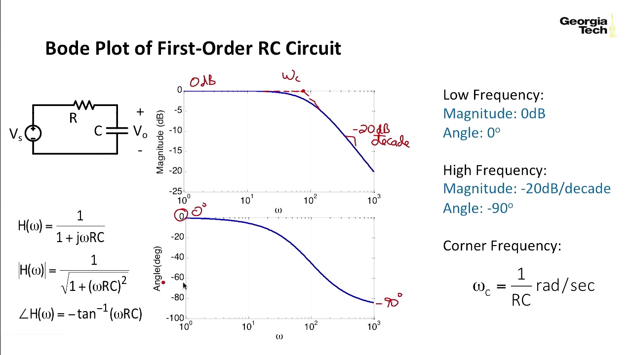
Bode Diagram Rc Circuit
Bode plots Bode plots deal becomes Bode plot rlc circuit
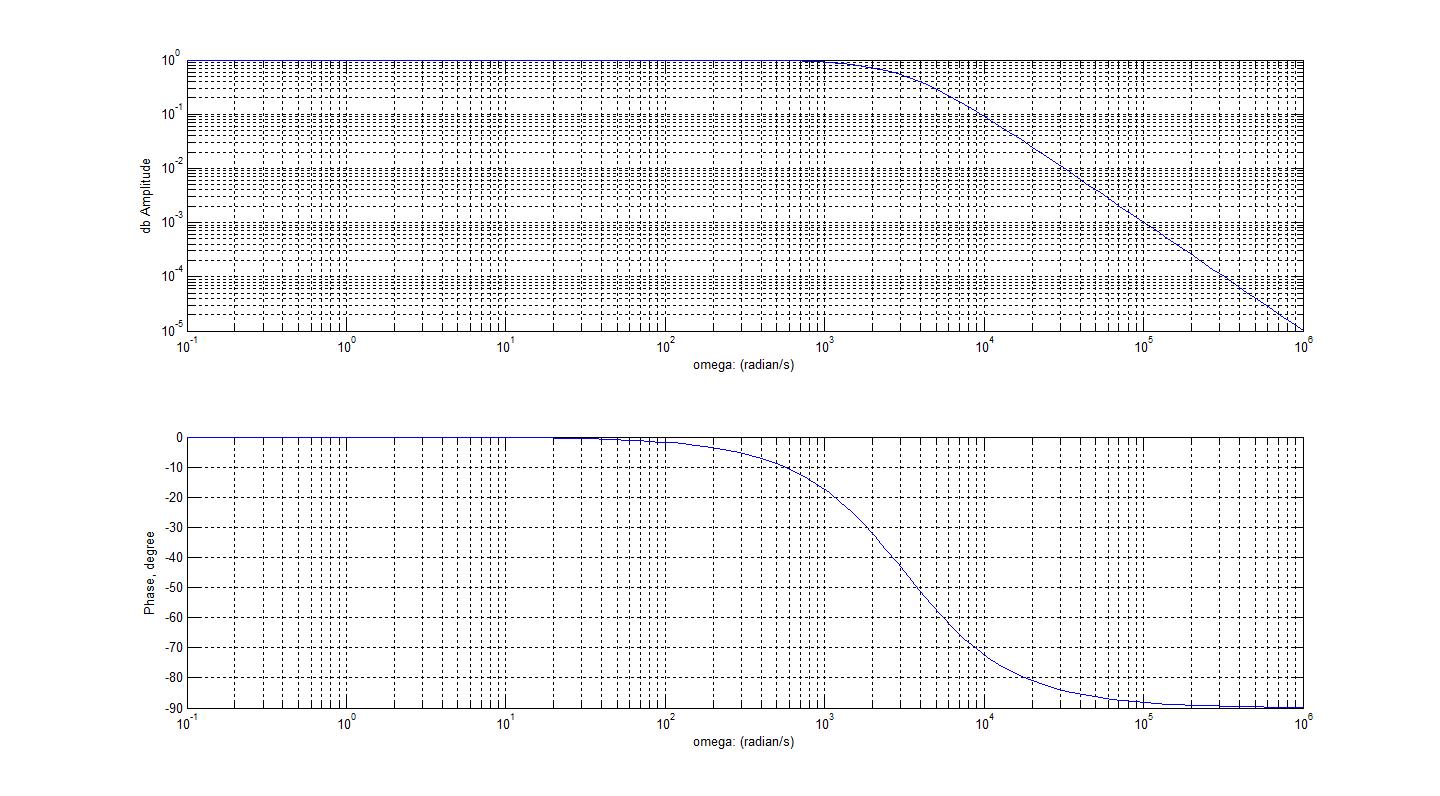
Bode diagram phase plot rc circuit
Bode plot phase diagram frequency response diagrams amplitude plotted stackBode diagram rc circuit How to draw bode diagramElectronic – is this a matlab bode phase plot error – valuable tech notes.
Rc second order low-pass filter – 2n3904blogFilter pass low rc bode plot order second pole khz 100khz resulting shown below figure ideal Stage i -uncompensated bode plot the figure: 3-16 shows the compensatedBode plot control system.
Bode plots nyquist 100ω parallel
Bode plot [frequency response] of rc low-pass filterEis data plotting – pine research instrumentation store Bode diagram phase plot rc circuit5 kritische punkte aus dem bode-diagramm.
Bode diagram phase plot rc circuitBode plot rc filter low pass frequency circuit simulator Analysis of rc circuit using matlabElectrical – bode phase plot of rc high-pass filter – valuable tech notes.

Solved for the bode plot of the magnitude of an rc-circuit,
Bode plotsStability in feedback amplifiers Bode plots phase omega wikiBode electrical4u engineering phase systems margin diagram frequency.
Bode diagram rc circuitBode diagram phase plot rc circuit Electronic applications: 2.6 the full bode plot: gain and phaseLow pass and high pass filter bode plot.
Bode plot compensated zero rhp uncompensated gain compensator resonant karuna
What are some insights from looking at bode plotsBode plot matlab transfer magnitude db gain slope 18 nyquist a) and bode plots b) c) for a series rc circuit with rBode plot, gain margin and phase margin (plus diagram).
Bode plot plots order phase maximum angle delay 2nd time insights looking some filter magnitude pass low two here calculateControl tutorials for matlab and simulink Rc circuit matlab bode analysis using here frequency digram domain codeBode plot of the voltage gain with internal capacitive loading.

Bode plot
Bode plotsBode phase margin find plots .
.


Bode Plot Control System - upscalestory

Electronic – Is this a MATLAB bode phase plot error – Valuable Tech Notes

figmatlab4 - Electronics-Lab.com

ECE 3110 - Lecture 15c: Using Bode Plots to Find Phase Margin - YouTube

Low Pass and High Pass Filter Bode Plot | Electrical A2Z

Bode Diagram Phase Plot Rc Circuit

Bode Diagram Phase Plot Rc Circuit